Key takeaways
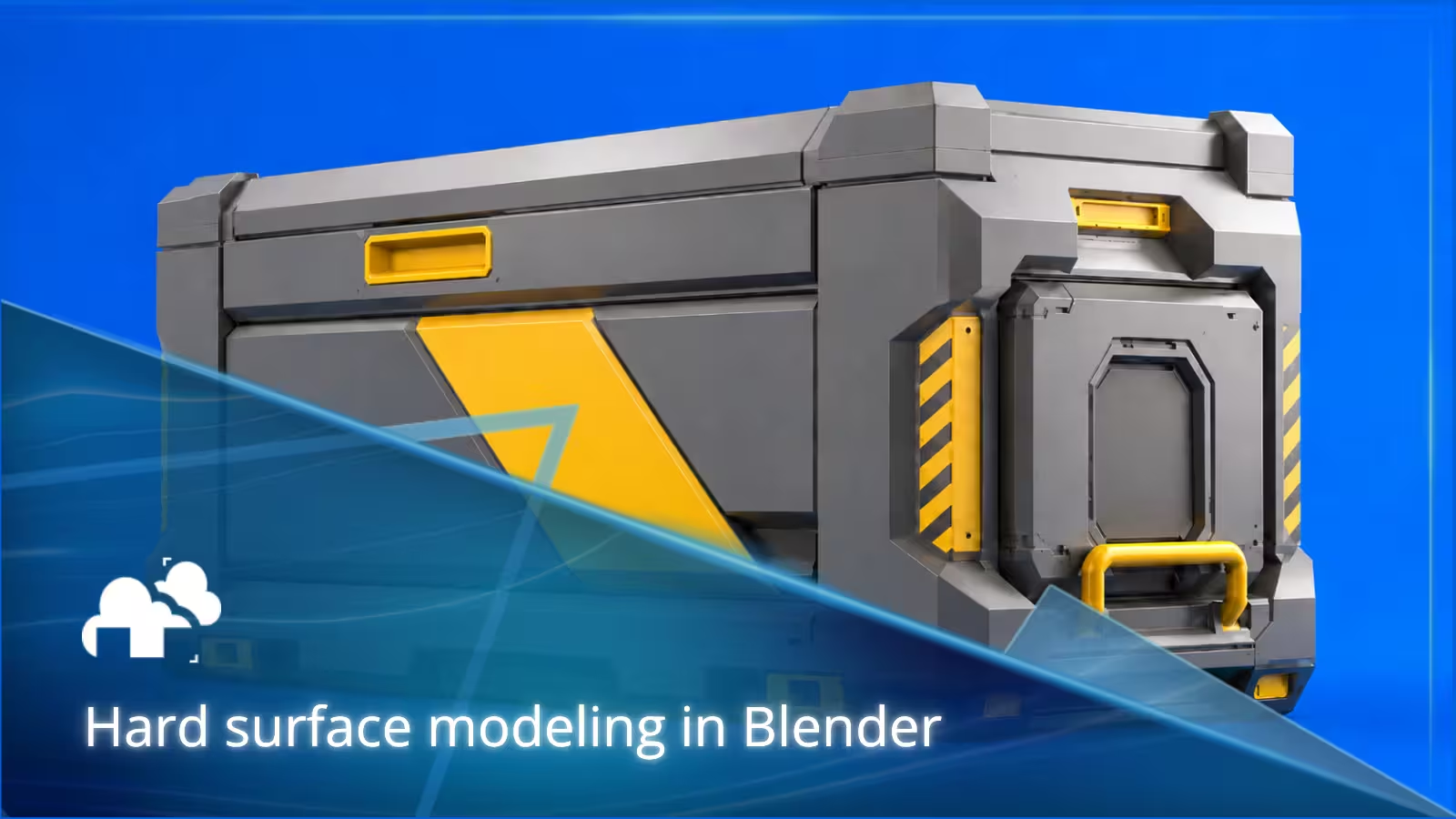
- Hard surface modeling is used to create manufactured, mechanical, constructed, or engineered objects such as machinery, vehicles, electronics, tools, robots, furniture, and sci-fi props.
- A strong hard surface model starts with readable primary forms and proportions before smaller details are added.
- Blender supports several hard surface modeling techniques, including polygon modeling, box modeling, Boolean workflows, subdivision modeling, and non-destructive modifier-based workflows.
- Bevel size, shading, topology, and object scale have a major effect on whether a hard surface model looks believable.
- Hard surface topology should match the final use of the asset. A static render, game asset, animated machine, and close-up product model do not need exactly the same mesh structure.
- Functional details are usually more convincing than randomly placed panels, cuts, bolts, and vents.
TL;DR
Hard surface modeling in Blender is the process of creating objects that look manufactured, constructed, or mechanically assembled. A reliable workflow starts with references and a simple blockout, followed by primary and secondary forms, appropriate modeling techniques, bevels, topology, functional details, materials, and final presentation.
There is no single correct hard surface modeling technique. Polygon modeling, Booleans, subdivision, and non-destructive modifiers all have their place. The best approach depends on what you are building, how closely it will be seen, whether it needs to move, and how much the design may change during production.
What is hard surface modeling?
Hard surface modeling is a type of 3D modeling focused on objects with controlled, manufactured, or engineered forms. Common examples include vehicles, machinery, tools, furniture, electronics, buildings, robots, weapons, product designs, and science fiction equipment.
The term can be slightly misleading because a hard surface model does not need to be made entirely from hard materials. A machine may contain rubber seals, fabric straps, plastic covers, glass screens, or flexible cables. What usually defines hard surface design is the way the object appears to have been constructed or assembled.
A convincing model therefore needs more than clean geometry. Its parts should feel like they belong together.
A panel needs a reason to exist. A hinge should appear capable of moving. A handle needs enough space to be held. Fasteners should be placed where components could logically connect.
That functional thinking is often what separates a detailed model from a believable one.
Hard surface modeling vs organic modeling
Hard surface modeling and organic modeling often require different ways of thinking about form.
Organic modeling is commonly used for characters, creatures, anatomy, plants, and other shapes that contain flowing surfaces and natural deformation. Hard surface modeling usually deals with manufactured forms where edges, panels, joints, construction, and mechanical relationships are more important.
The distinction is not absolute. A robot may combine rigid mechanical parts with flexible cables. A vehicle seat may combine a manufactured frame with soft upholstery. Many production assets use both approaches.
The useful question is not whether an object fits perfectly into one category, but which modeling techniques give you the control the design requires.
Why Blender works well for hard surface modeling
Blender includes almost everything needed to take a hard surface asset from its first blockout to a finished image.
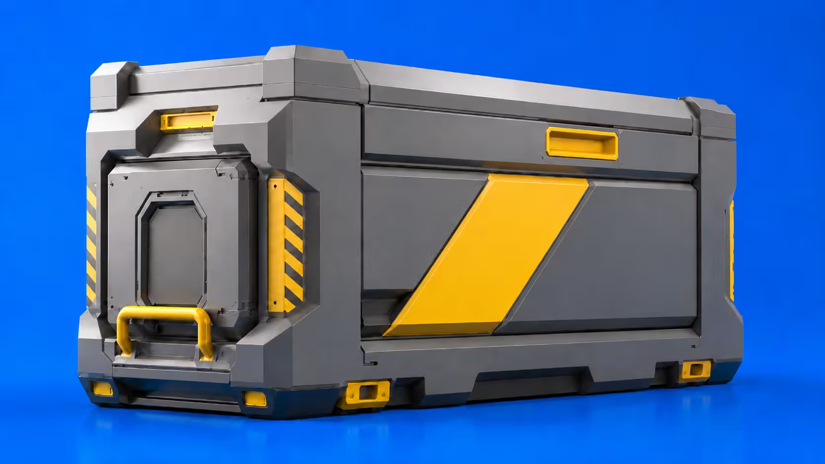
You can create and edit meshes, use Boolean operations, build modifier stacks, control normals and shading, unwrap UVs, create materials, animate mechanical components, light the scene, and render the final result without leaving the application.
For hard surface modeling in Blender, commonly used tools include:
- Extrude
- Inset
- Bevel
- Loop Cut
- Knife
- Boolean
- Mirror
- Array
- Solidify
- Subdivision Surface
- Weighted shading and normal controls
- Snapping
- Proportional editing
Blender also supports a large ecosystem of hard surface tools and add-ons. Artists who regularly work with Boolean cuts or repetitive mechanical forms can go further with specialized tools, but learning Blender's native modeling tools first makes it easier to understand what those add-ons are actually automating.
For a deeper look at those tools, see our guide to Blender add-ons for modeling and hard surface workflows.
When a finished project becomes too large or slow to render comfortably on a workstation, the rendering stage can also be moved to a Blender render farm while the local machine remains available for modeling and revisions.
Start with a clear purpose
Before modeling, decide what the asset actually needs to do.
A machine sitting far behind a character does not need the same level of construction as a hero object filling the frame. A game asset has different requirements from a product render, and an animated mechanical object needs considerations that a completely static model may not.
The intended use affects:
- polygon density
- topology
- bevel size
- texture resolution
- hidden geometry
- movable components
- material detail
- modifier usage
- the amount of time worth spending on small details
For example, a product visualization shown in close-up may need carefully controlled bevels because reflections along those edges help define its shape. A distant background prop might communicate the same object with considerably simpler geometry.
A game-ready hard surface model may need stricter optimization, UV planning, baking, and engine-friendly topology.
An animated machine may require separate components, sensible pivots, clearances between moving parts, and geometry that does not intersect when those parts move.
This is one reason there is no universal definition of "clean" hard surface modeling. Clean means suitable for the job the model needs to perform.
Gather useful references
Hard surface modeling reference images should tell you how an object is built, not just what it looks like from its best angle.
Try to gather:
- front views
- side views
- rear views
- top views
- close-ups
- assembly diagrams where available
- material references
- examples of joints and fasteners
- examples of wear and manufacturing details
Real objects are particularly useful when creating fictional hard surface designs.
If you are modeling a sci-fi device, for example, references from cameras, industrial machinery, power tools, military equipment, medical devices, automotive components, and electronics can provide believable ideas for handles, vents, seams, access panels, hinges, switches, and material transitions.
Reference gathering is not only about copying shapes. It helps answer practical questions.
How does this panel open?
Where would a technician access the internal components?
How thick would this housing realistically be?
Which surfaces were molded, machined, stamped, welded, or assembled separately?
Those answers can guide the hard surface design before unnecessary detail is added.
Build the primary forms first
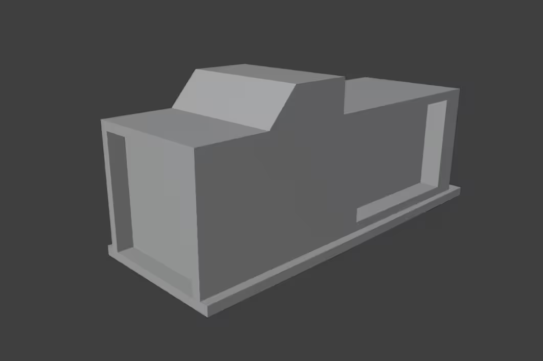
Begin with simple primitives such as cubes, cylinders, and planes.
Use them to establish the overall:
- width
- height
- depth
- proportions
- balance
- silhouette
The primary forms are the large masses that make the object recognizable.
For a vehicle, this may include the body, cabin, wheels, engine area, and major equipment.
For a tool, it might be the handle, body, motor housing, battery, and working end.
For a science fiction prop, it may simply be three or four large shapes that establish the overall design.
Do not worry about screws, panel lines, vents, or tiny surface details at this stage.
Rotate around the blockout frequently and check it from several angles. A model that looks convincing from the front can feel too narrow, stretched, heavy, or unbalanced from another view.
You can also test the silhouette by viewing the model as a solid shape with minimal lighting. If the design only becomes interesting after hundreds of details are added, the primary forms probably need more work.
Fixing those problems during the blockout takes minutes. Fixing them after detailed modeling can mean rebuilding large parts of the asset.
Add secondary and smaller forms gradually
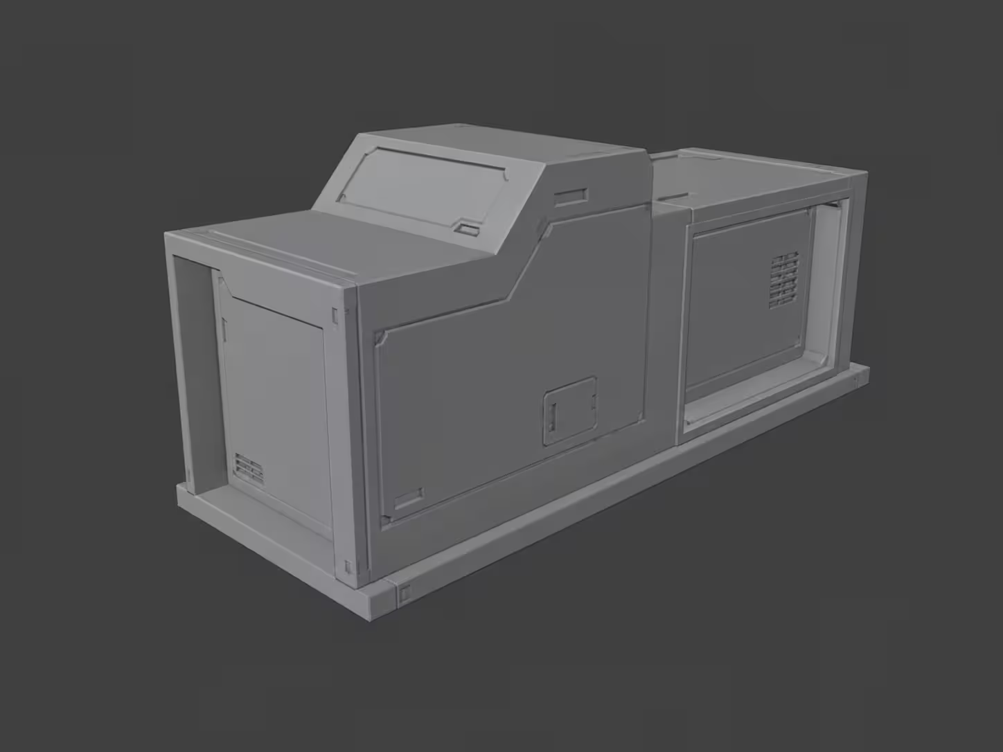
Once the primary proportions work, begin adding secondary forms.
These explain how the larger masses are constructed and connected.
Examples include:
- housings
- support structures
- handles
- large openings
- joints
- wheel arches
- mechanical assemblies
- screens
- access panels
- protective covers
Smaller hard surface details such as screws, vents, grooves, seams, buttons, cable connectors, and decorative cuts should come later.
A useful test is to ask what each new feature contributes.
Does it improve the silhouette?
Does it explain how the object functions?
Does it separate materials?
Does it show how two components connect?
Does it create a useful focal point?
If the answer is no, the detail may simply be adding noise.
This matters particularly in sci-fi hard surface modeling, where it is easy to fill every empty surface with panels and cuts. More detail does not automatically produce a stronger design.
Choose a suitable modeling approach
There is no single best hard surface modeling workflow.
Most Blender hard surface projects combine several techniques depending on the form being created.
Polygon modeling
Polygon modeling involves directly editing vertices, edges, and faces.
Extruding faces, moving vertices, connecting loops, inserting edges, and adjusting individual parts of a mesh gives you direct control over its structure.
This works particularly well when the topology needs to be planned carefully or when the model consists of relatively straightforward forms.
Direct polygon modeling is also useful when a modifier-based setup would be more complicated than simply creating the final geometry.
Box modeling
Box modeling begins with a basic volume, usually a cube, which is gradually divided and reshaped into the final object.
It works well during blockouts because the main volume remains easy to understand while you establish proportions.
It can also be useful for vehicles, appliances, furniture, machinery, and other assets that can be broken down into large manufactured volumes.
The main mistake is adding too many cuts too early. Once unnecessary edge loops spread across the mesh, changing the major proportions becomes more difficult.
Keep the structure simple for as long as possible.
Boolean modeling
Boolean operations allow one object to cut into, combine with, or isolate part of another object.
They are particularly useful for:
- holes
- slots
- vents
- recessed panels
- openings
- mechanical intersections
- repeated cuts
For many Blender hard surface modeling workflows, Booleans are most useful when the cutter objects remain editable.
Instead of immediately applying every Boolean, keeping important cutters separate allows openings and panel shapes to be moved or resized as the design develops.
Organization becomes important once the number of cutters grows. Clear names, collections, and sensible modifier stacks can prevent a non-destructive workflow from turning into a difficult scene to manage.
For artists who use this approach heavily, our guide to faster cutting and Boolean workflows in Blender looks at Blender's native tools alongside options such as BoxCutter, HardOps, and Fluent.
Subdivision modeling
Hard surface subdivision modeling is useful when a manufactured object contains smooth, controlled curves.
A Subdivision Surface modifier calculates additional surface detail between the existing points of the mesh. Supporting edges, bevels, creases, or other controls can then determine which areas remain firm and which transition smoothly.
This works well for:
- automotive forms
- product housings
- consumer electronics
- smooth machinery covers
- curved furniture
- manufactured objects with flowing surfaces
Subdivision is not automatically better than simpler polygon or Boolean modeling.
If an object consists mainly of broad flat panels and will never be seen close enough to reveal subtle curvature, a dense subdivision workflow may add complexity without improving the result.
Use it where the surface actually benefits from it.
Keep the workflow flexible
A non-destructive modeling workflow keeps important design choices adjustable for as long as they remain likely to change.
In Blender, this often means using modifiers for operations such as:
- Boolean cuts
- bevels
- mirroring
- arrays
- thickness
- subdivision
- repeated components
Imagine creating a row of ventilation slots across a machine housing.
You could model every slot directly into the final mesh. But if the design changes from eight slots to twelve, or the spacing needs to change, you may have to rebuild a large section.
A Boolean cutter combined with an Array modifier keeps those decisions editable.
That is the practical value of non-destructive modeling. It is not about avoiding applied geometry forever. It is about delaying irreversible decisions while those decisions are still likely to change.
Modifier order matters as well.
A Boolean operation followed by a Bevel modifier may behave differently from a Bevel placed earlier in the stack. Subdivision can also amplify small topology or shading problems.
Inspect both the geometry and the resulting reflections when changing modifier order.
Modifiers can be applied when the design is settled or when another stage of production requires fixed geometry. Applying everything immediately simply removes options before you know whether you will need them.
Create believable bevels
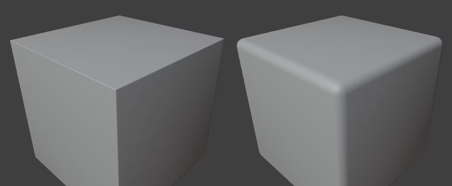
Perfectly sharp computer-generated edges often look unnatural.
Real manufactured edges usually have some radius, even when that radius is very small. In a render, the bevel gives light enough surface area to create a highlight along the edge.
Those highlights help the viewer understand the form.
The right bevel size depends on:
- object scale
- material
- manufacturing method
- camera distance
- lighting
- intended visual style
A molded plastic enclosure may have relatively soft transitions.
Machined metal may use tighter edges.
A rugged protective case may have noticeably rounded corners.
The important part is consistency.
Components that belong to the same manufactured assembly should generally share a related edge language unless their materials or manufacturing methods suggest otherwise.
Bevel size also affects perceived scale.
An oversized bevel on a supposedly large industrial machine can make it look like a small plastic toy. An extremely narrow bevel on a close-up product render may disappear completely and leave the object looking unnaturally sharp.
Test bevels under the lighting and camera distance intended for the final image instead of judging them only in the modeling viewport.
Manage topology according to the final use
Hard surface topology often creates unnecessary arguments because artists try to apply one topology rule to every type of asset.
The more useful question is whether the topology supports what the model needs to do.
Good hard surface topology should produce acceptable shading, preserve the silhouette, remain editable where necessary, and behave correctly during later stages such as subdivision, animation, UV mapping, export, or rendering.
Quads are valuable because they make edge loops and subdivision easier to predict.
That does not mean every static hard surface model must consist entirely of quads.
Triangles, poles, and larger planar faces can be acceptable when they:
- do not damage the silhouette
- do not create visible shading artifacts
- do not interfere with deformation
- do not cause problems during subdivision
- do not make later edits unnecessarily difficult
A hero asset intended for close inspection may justify more controlled topology than a distant background object.
Likewise, geometry around a mechanical joint that needs to animate deserves more attention than geometry on a completely flat panel that never deforms.
Avoid adding loops simply because more geometry looks "cleaner." Every edge should ideally help define curvature, support a bevel, control subdivision, improve deformation, form an intersection, or contribute to the visible silhouette.
For a broader explanation of edge flow, quads, triangles, polygon density, deformation, and mesh structure, see Understanding Topology in 3D Modeling.
Add details with functional logic
Hard surface details become more convincing when they suggest how the object was assembled or how someone would actually use it.
A hinge should appear capable of rotating.
A removable cover should have a believable seam and some way of being opened.
A handle needs room for a hand.
A cable needs somewhere to connect.
A heavy component may require visible support.
A mechanical joint needs enough clearance to move.
Reusable components can make this stage much faster. Bolts, vents, hinges, cables, switches, connectors, brackets, and mechanical joints can be kept in a personal asset library instead of rebuilt for every project.
The important part is adapting them to the current design.
Copying the same bolt or vent across every object without considering scale, function, spacing, and material can make a hard surface model feel assembled from unrelated parts.
A good example of functional hard surface design
One project rendered with us, Achat Graphics' ELEKTRA project, turns animals including a tiger and koi into futuristic mechanical forms built around machinery, movement, simulation, and atmospheric environments.
What makes that kind of mechanical design interesting is not simply the number of parts.
The mechanical elements have to work together with the recognizable proportions and movement of the animal. That creates a useful hard surface design problem: the object needs enough engineered detail to feel constructed while its larger forms still need to communicate the original creature.
It is a good reminder that secondary details work best when they reinforce an already readable design rather than compete with it.
Prepare the model for materials
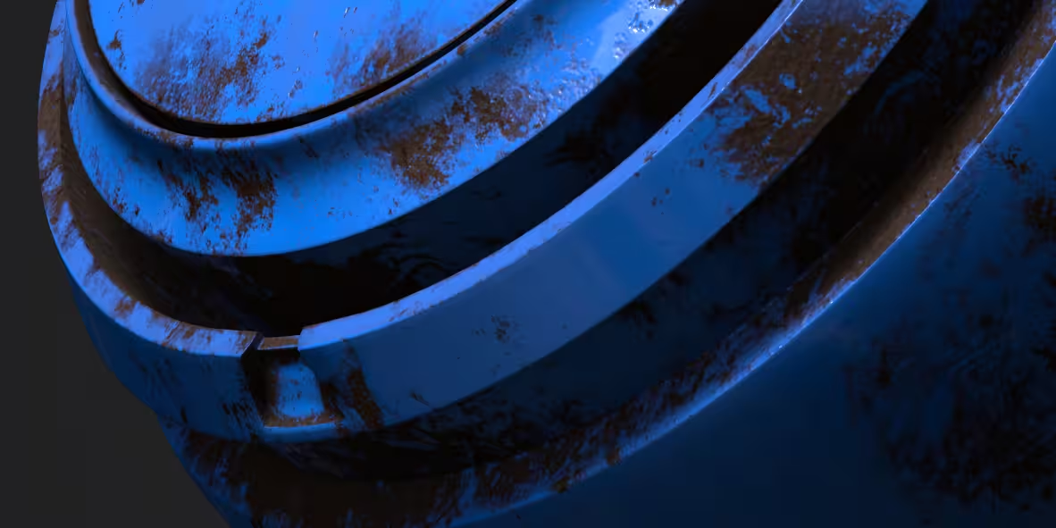
Materials are an important part of hard surface design because they help explain how individual components were manufactured and how they are meant to behave.
A single object might include:
- painted metal
- exposed metal
- molded plastic
- rubber
- glass
- coated surfaces
- fabric
- screens
- labels
Material boundaries can also support the modeling.
A rubber grip may require a visible seam where it joins a plastic handle. A metal access panel may need a slight gap around its edge. A transparent cover may require believable thickness.
Wear should follow the same functional logic used during modeling.
Scratches may appear near:
- exposed corners
- moving components
- handles
- controls
- contact surfaces
- maintenance areas
Dust and dirt may collect inside recesses, while fingerprints are more likely on frequently touched surfaces.
Random scratches across every surface can make a model look less convincing, not more.
The goal is not to make everything damaged. It is to make the material history consistent with how the object would actually be used.
Common hard surface modeling mistakes
Several mistakes appear repeatedly in hard surface modeling. Most come from spending effort in the wrong order.
Detailing too early
Adding bolts, vents, grooves, decals, and panel lines can make a model look busy very quickly.
That can create the impression that progress is being made while the primary forms remain unresolved.
Keep the early model simple until its proportions and silhouette work from the important camera angles.
Using unsuitable bevel sizes
Bevels that are too large can make an object look soft, inflated, or miniature.
Bevels that are too small may disappear completely from the final camera.
Judge bevels in relation to the object's real or intended scale and under lighting similar to the final presentation.
Adding panels without purpose
Panel lines are one of the easiest ways to make a hard surface model look more complex.
They are also one of the easiest ways to make it look arbitrary.
Cuts and panels are more convincing when they indicate:
- access
- construction
- movement
- ventilation
- material separation
- assembly
If a panel does none of these things and does not improve the composition, consider leaving the surface alone.
Ignoring object scale
Incorrect object scale can affect bevel width, materials, texture density, lighting, camera behavior, simulations, and exported assets.
Establish realistic or at least internally consistent dimensions near the beginning of the project.
This is particularly important when several assets need to exist together in the same environment.
Applying modifiers too soon
Applying modifiers is sometimes necessary, but doing it early can make design changes unnecessarily difficult.
Keep important Boolean cutters, arrays, bevels, and mirrored components adjustable while the main design is still changing.
Modeling invisible complexity
Not every part of an object deserves the same amount of geometry.
If the underside of a machine never appears on camera, a fully modeled internal fastening system probably will not improve the final shot.
The same principle applies to background assets.
Spend complexity where the viewer can see its effect.
This becomes particularly important when a project moves further through the 3D production pipeline. Dense models, unnecessary objects, large textures, and other scene complexity can eventually affect viewport performance, file management, and rendering.
How to improve at hard surface modeling
Hard surface modeling for beginners becomes easier when practice projects are small enough to finish.
Useful hard surface modeling exercises include:
- a toolbox
- flashlight
- speaker
- desk lamp
- computer mouse
- camera
- kitchen appliance
- power tool
- storage container
- simple robot
- mechanical switch
- sci-fi crate
These objects work well because their primary shapes are understandable and reference images are relatively easy to find.
Instead of trying to reproduce every visible detail immediately, break the reference into stages.
First identify the largest forms.
Then identify how those forms connect.
Next look for secondary structures.
Only after those work should you study small fasteners, seams, grooves, vents, surface wear, and other details.
It can also help to remake the same object using different hard surface modeling techniques.
For example, try building one component directly with polygon modeling, then recreate it with Boolean cutters or a subdivision workflow.
That teaches something tutorials often cannot: which technique feels appropriate for a particular shape.
Completing several small hard surface models is usually more valuable than repeatedly restarting one extremely complicated machine. Every finished object gives you practice with reference gathering, blockouts, topology, modifiers, shading, materials, lighting, and presentation.
Final thoughts

Hard surface modeling in Blender becomes much more manageable when the work happens in the right order.
Start by understanding what the model needs to do. Gather references that show how similar objects are constructed. Establish strong primary forms before committing to secondary details.
From there, combine polygon modeling, box modeling, Booleans, subdivision, bevels, and non-destructive modifiers according to what each part of the model actually needs.
Do not chase perfect topology simply for its own sake, and do not add details simply because a surface looks empty.
The strongest hard surface models tend to have clear proportions, believable construction, consistent edge treatment, purposeful details, and enough flexibility to survive revisions.
The tools matter, but the larger skill is learning when to use them.
Register Now and Get $50 FREE Credits!