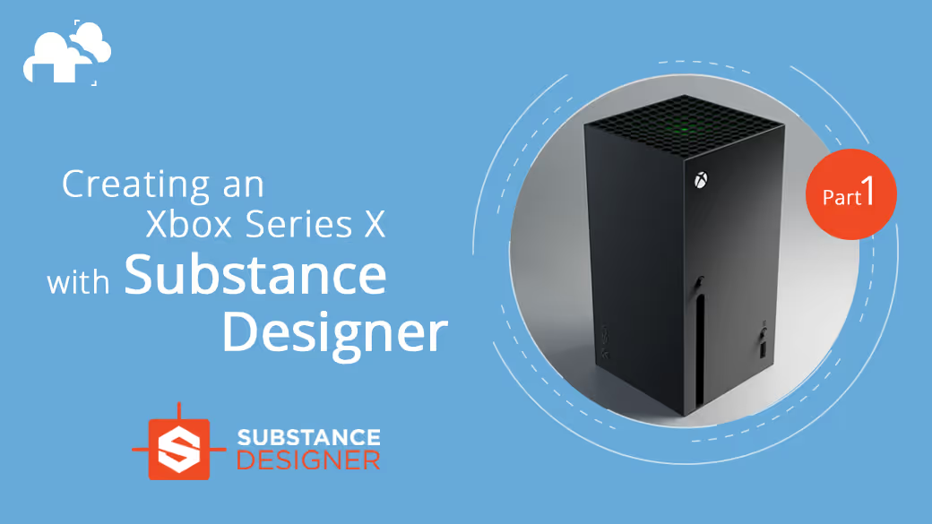
Substance Designer is known for authoring procedural materials. It can be used for creating tiles, and even to some extent procedural modeling! But is it possible to substitute high poly models by only creating a texture in Designer? Let's find out! In this video series and article, we’ll be taking a look at how to create an Xbox Series X inside Substance Designer.
Set up
Before we get started, there are a couple of things we have to set up:
1. Download the node, Auto Chamfer from Artyom Sarkisyan.

This node will be used for adding bevels to the mesh.
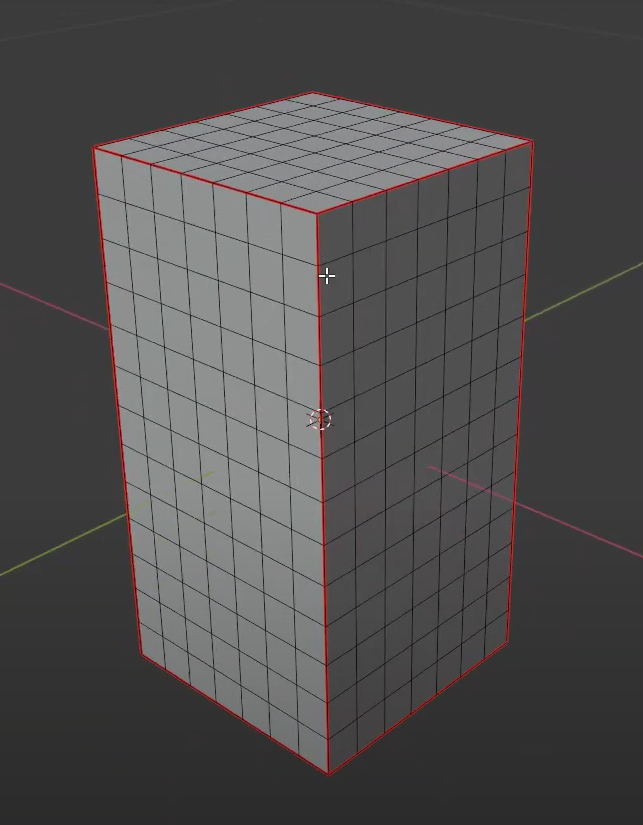
2. Set up the mesh
a .Dimensions: 15.1cm x 15.1cm x 30.1cm
b. Evenly spaced edge loops for tesselating:
c. UV Layout:

Setting up the Graph in Designer
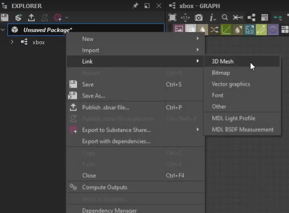
Import the 3D Mesh by right-clicking on the package > Link > 3D Mesh, then right-click and drag into the 3D view.
Open the resources folder, right-click on the mesh, then bake model information.

Bake out the curvature map and the UV to SVG map.
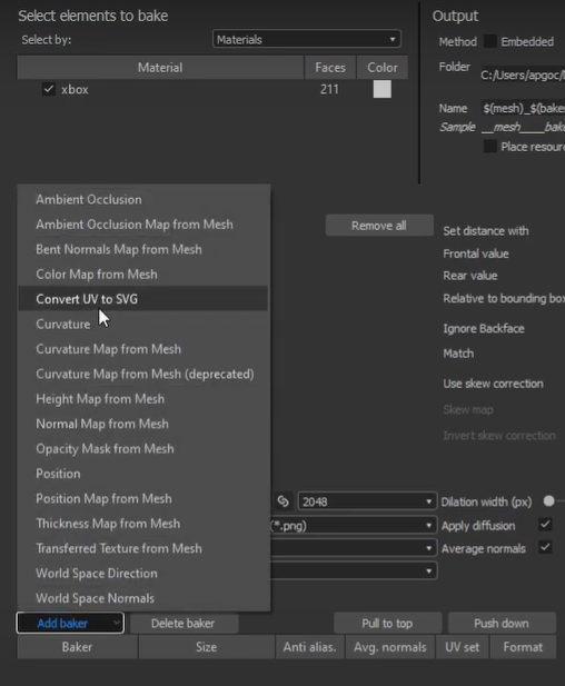
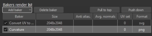
Import Auto Chamfer node to the graph.
Drag in the bake maps and connect to the Auto Chamfer node (to add bevels based on the UVs through the bake maps).
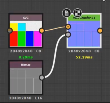
Connect the Auto Chamfer node’s output to the normal output.
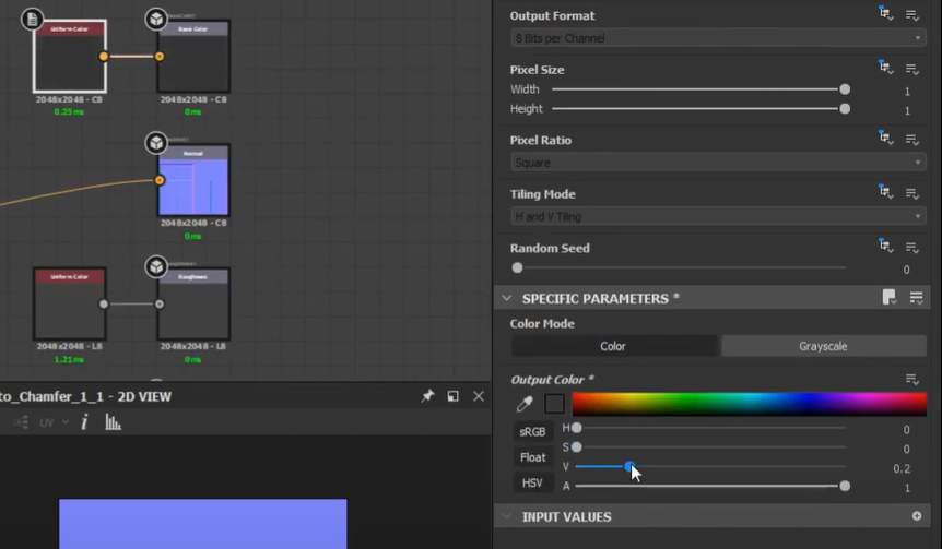
Set the Base Color to a darker value and set the Metallic value to white.
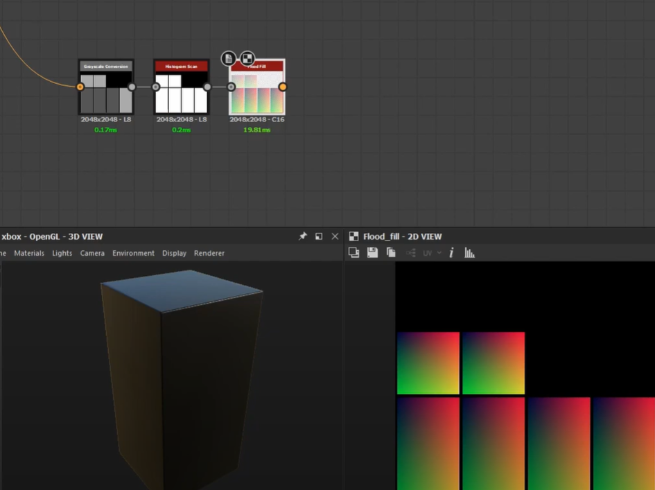
Convert UVs to SVG map to grayscale (grayscale conversion), connect that to a histogram scan (to make everything white), then plug that into a flood fill node to help visualize the UVs and the masking.
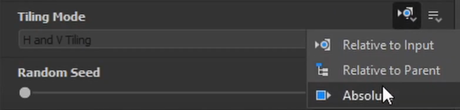
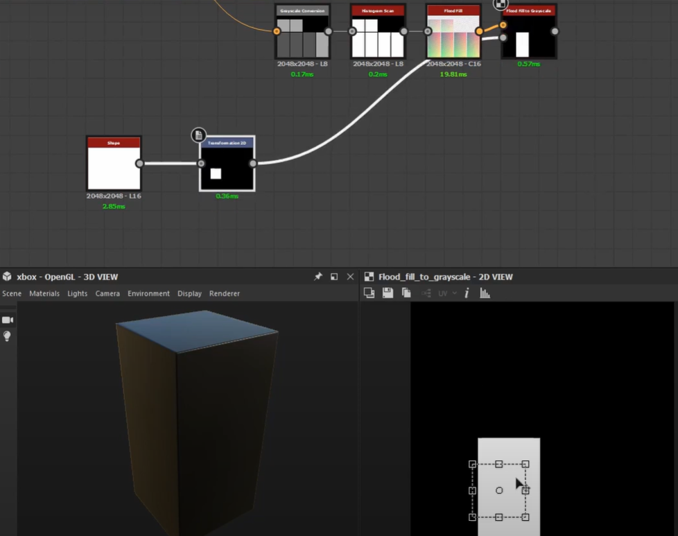
Get a Flood Fill to Grayscale Node, Shape node, and Transformation 2D node and plug the shape and transformation 2D into the grayscale input. Then set the Tiling Mode to No Tiling. This will allow us to use the square from the shape node as a selector.
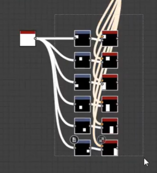
Copy and paste those nodes and make a selection for each UV.
Making the Top Shroud of the Xbox
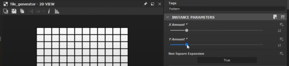
Add in a tile generator and set the X and Y amount to 12 (the number of holes on the real Xbox Series X).
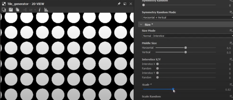
Change the Pattern to Disc then scale it down a bit.
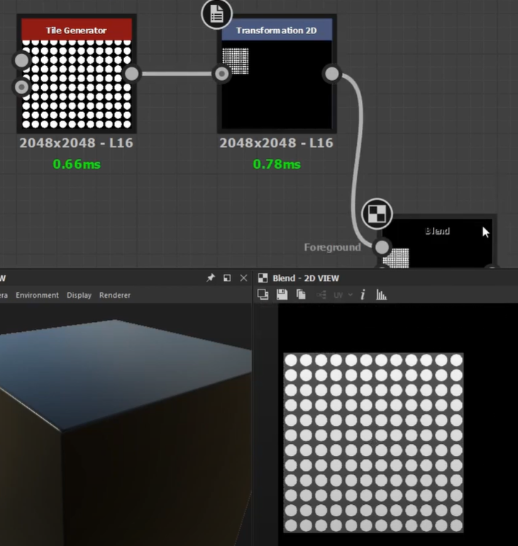
Connect that to a transformation 2D node and you can press CTRL + SHIFT and drag on the corners to resize it evenly then set the Tiling Mode to No Tiling.
Use a Blend Node in order to help us visualize where to place it. Connect our Transformation 2D Node here with the mask we made for the top and set the opacity down so we can see through it.


Align our Transform 2D node with the mask. In order for this to work, blend in a uniform color and set it to grayscale, then set the value to 0.5.
To activate tessellation, go to materials, switch from Parallax Occlusion to Tesselation, then set the tesselation factor to a high number and scale it up a bit. This will eat up performance though so be careful not to set it too high.
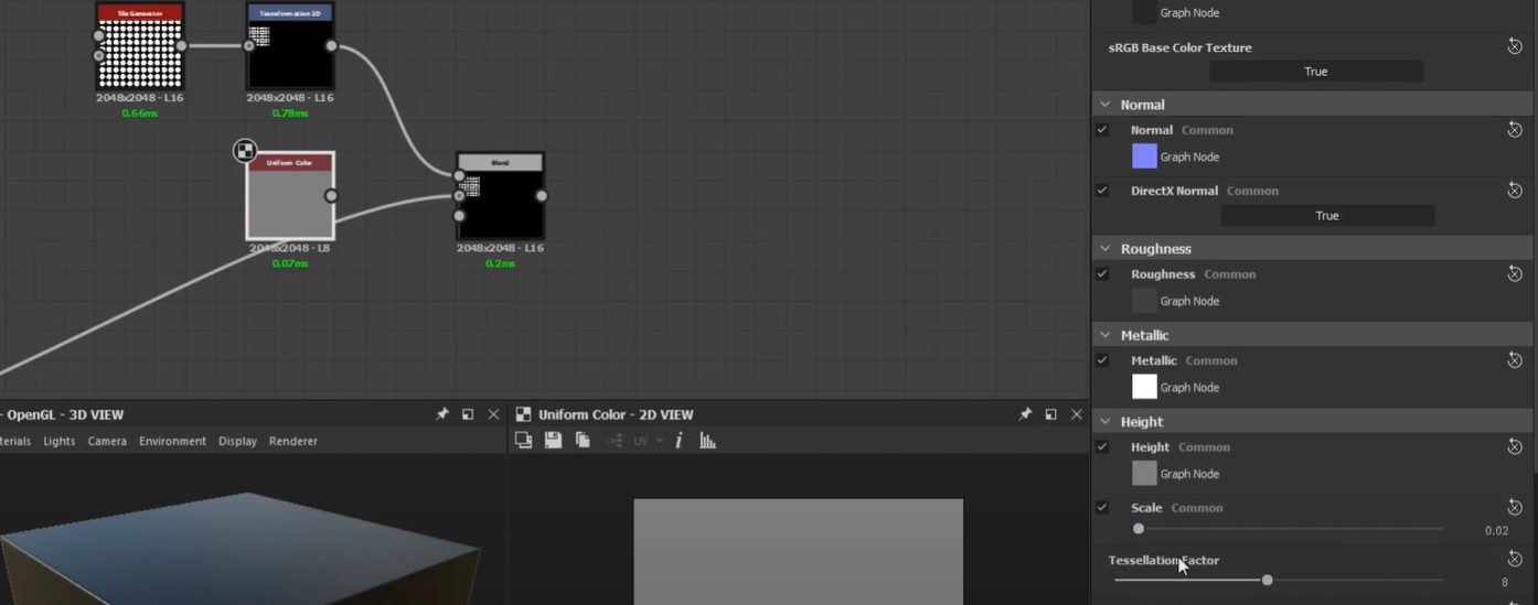
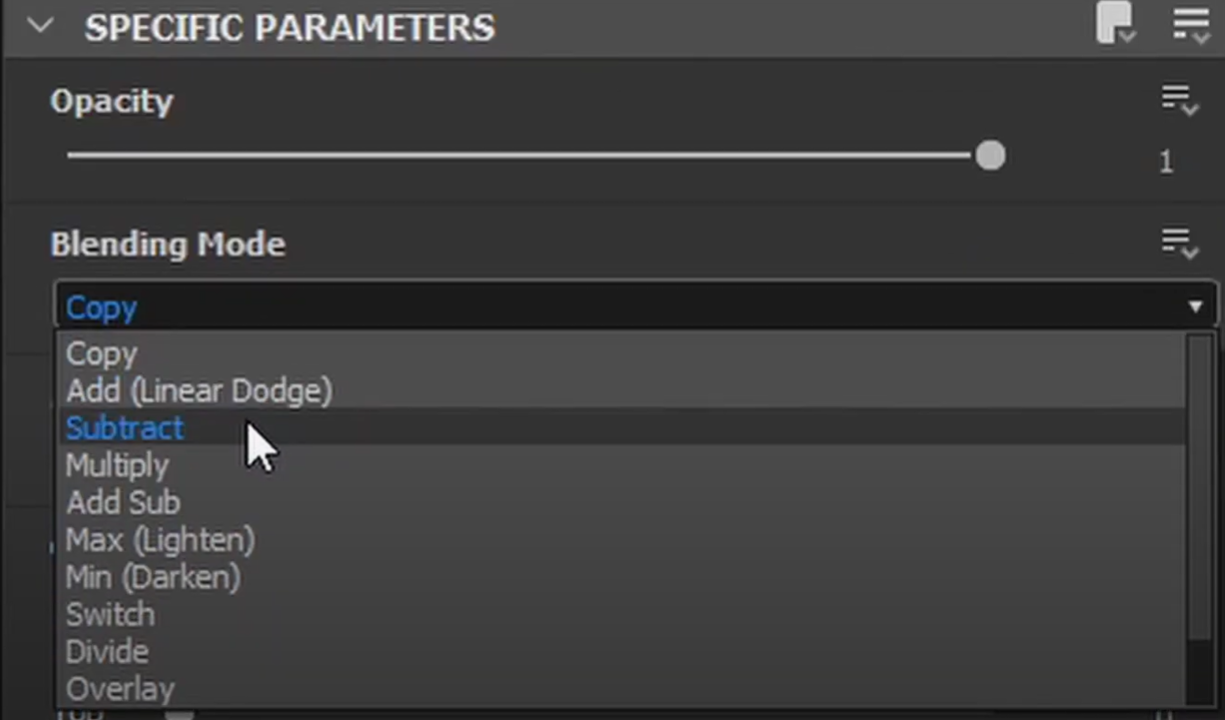
Going back to the blend node, just connect the uniform color and set the blending mode to subtract. Gray is our middle value, a darker value extrudes inward, and a lighter value extrudes outward.
Connect the blend node to the height output, then plug it into a normal node, and then use normal combine to blend it with our auto chamfer.
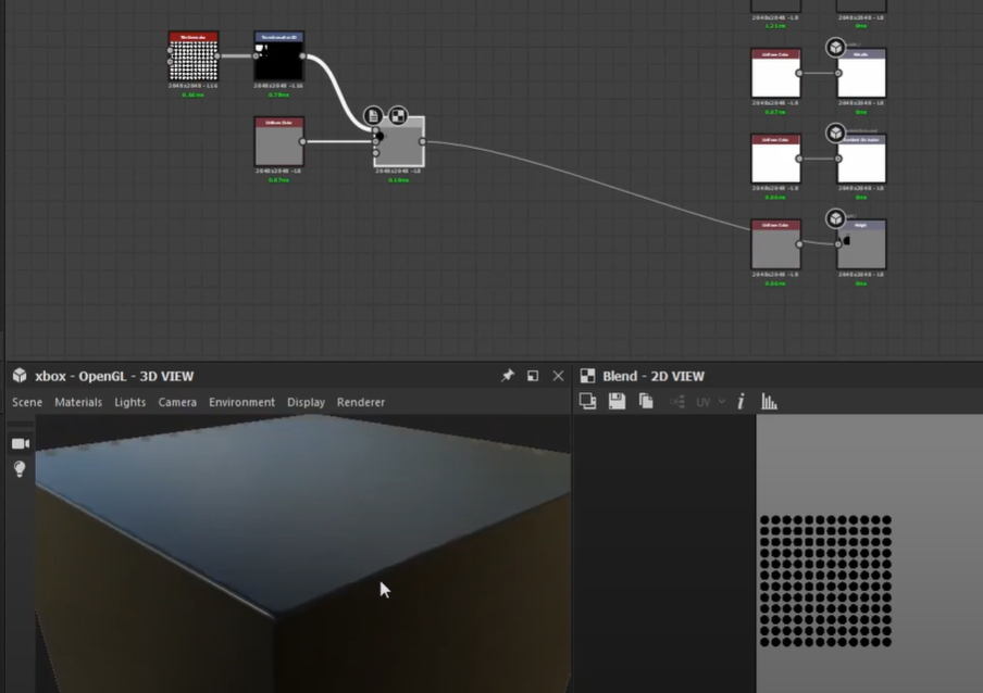
Connect the normal combine to our normal output and now we can see it’s working. We can go back to our transform 2d node and CTRL + SHIFT Drag to scale it down a bit.
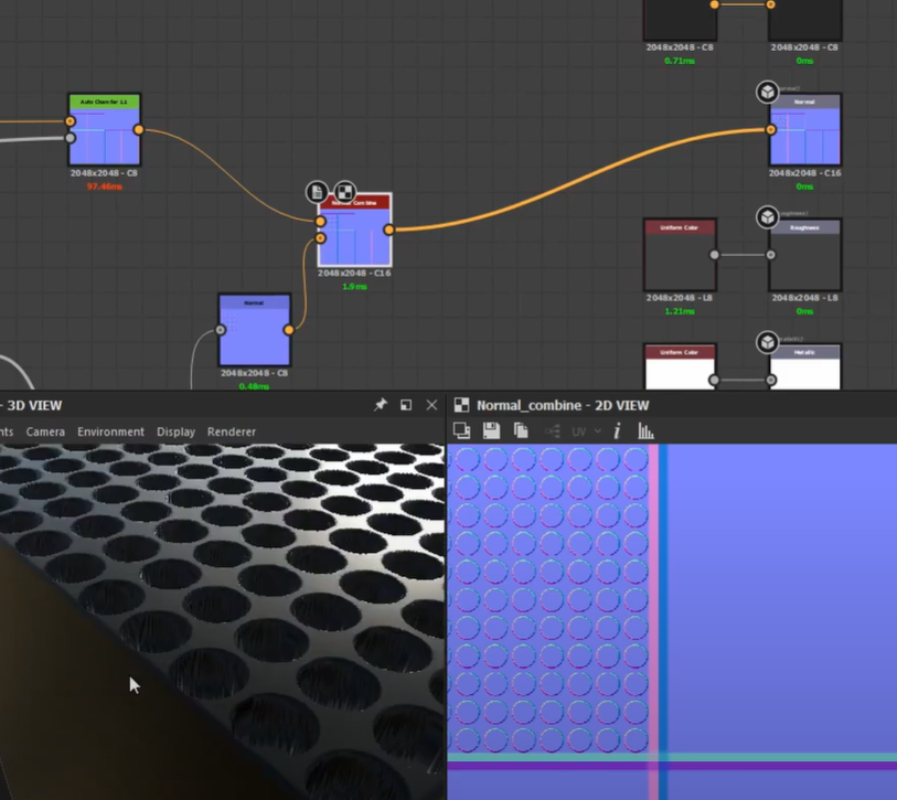

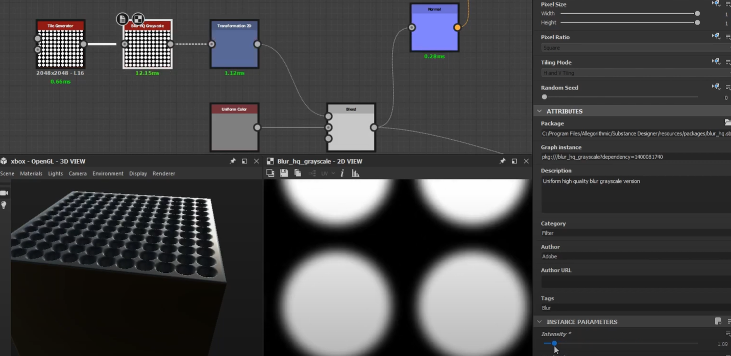
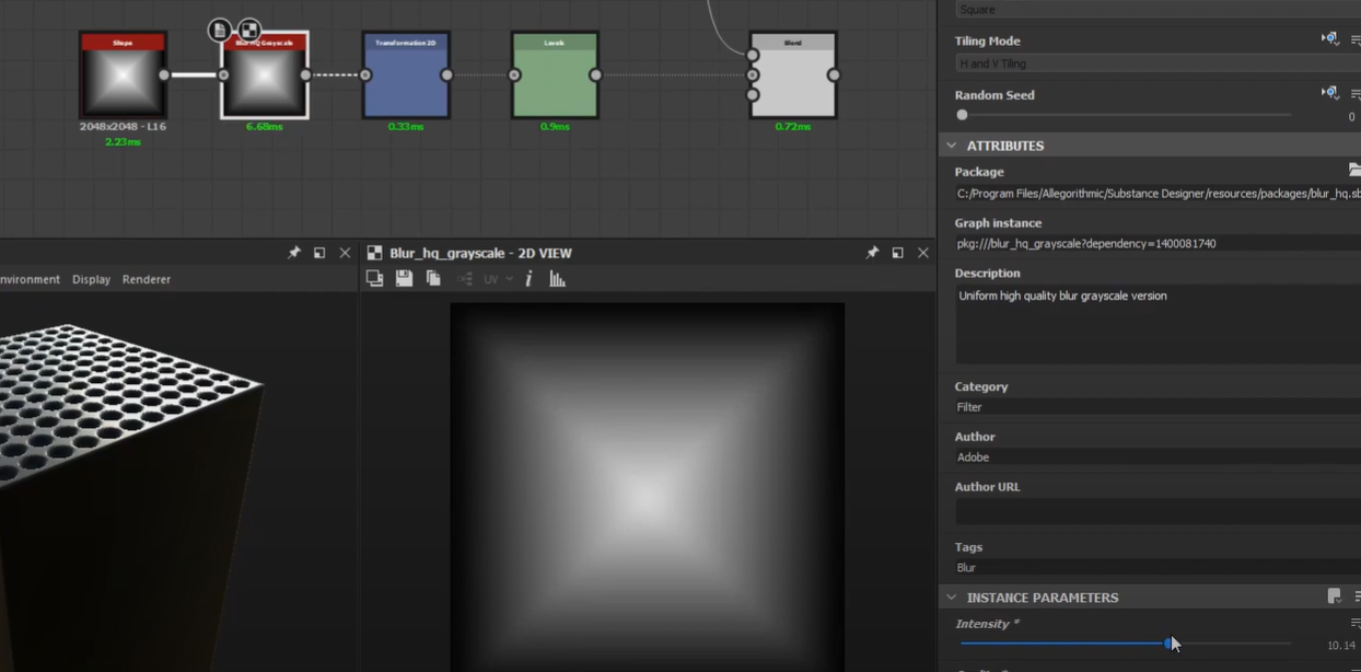
Plugging in a Blur HQ Grayscale node here can give a more beveled edge on those top holes. Adjust parameters as needed.
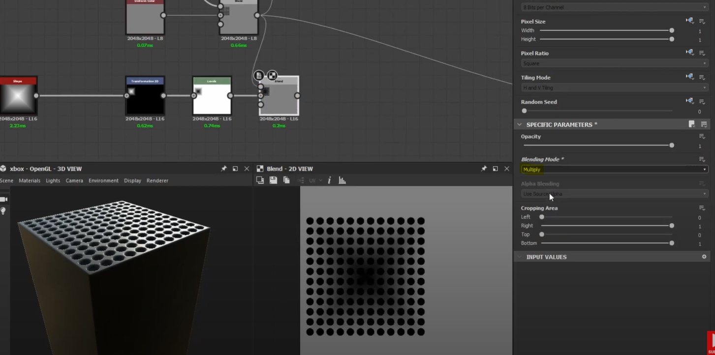
With the holes done, we can now try doing that gentle curve. Add in a shape node, set it to the pyramid, then duplicate the transform 2d we used for the tile generator and connect the pyramid there.
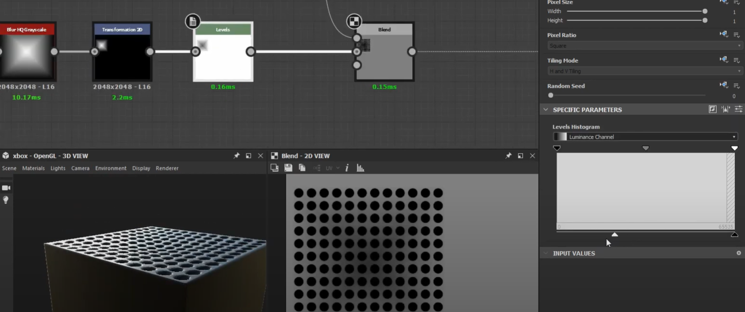
Use Levels and then click on this icon to invert.
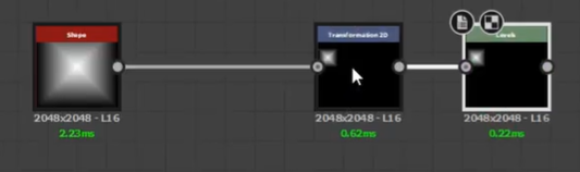

Blend that with our height map and set it to multiply.
Using a Blur HQ Grayscale here can help soften those sharp edges. Plug that into our height output and adjust as needed.

We can use the levels node to control the strength of the curve.
Emissive Map
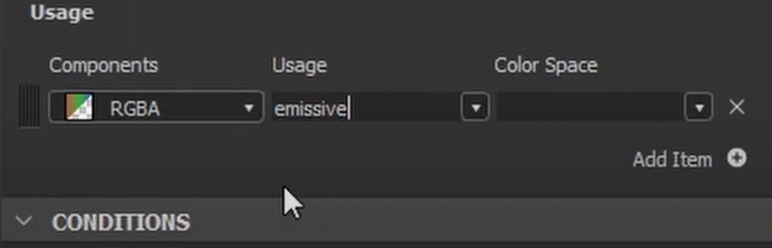
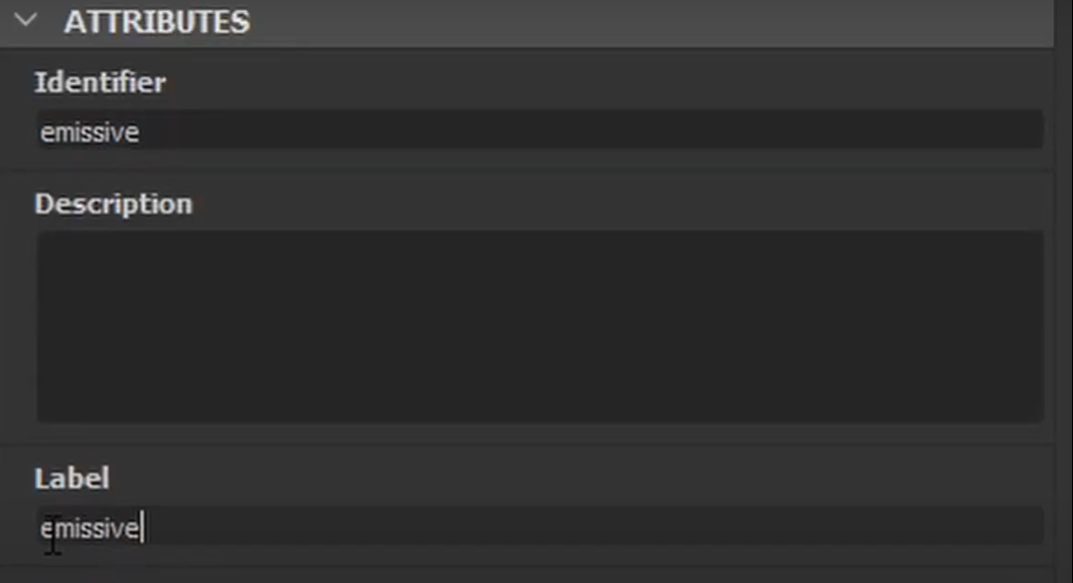
Add in an Output node, set the Usage Type to emissive, then just copy and paste that into our identifier and label.
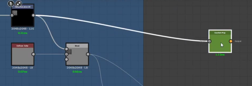
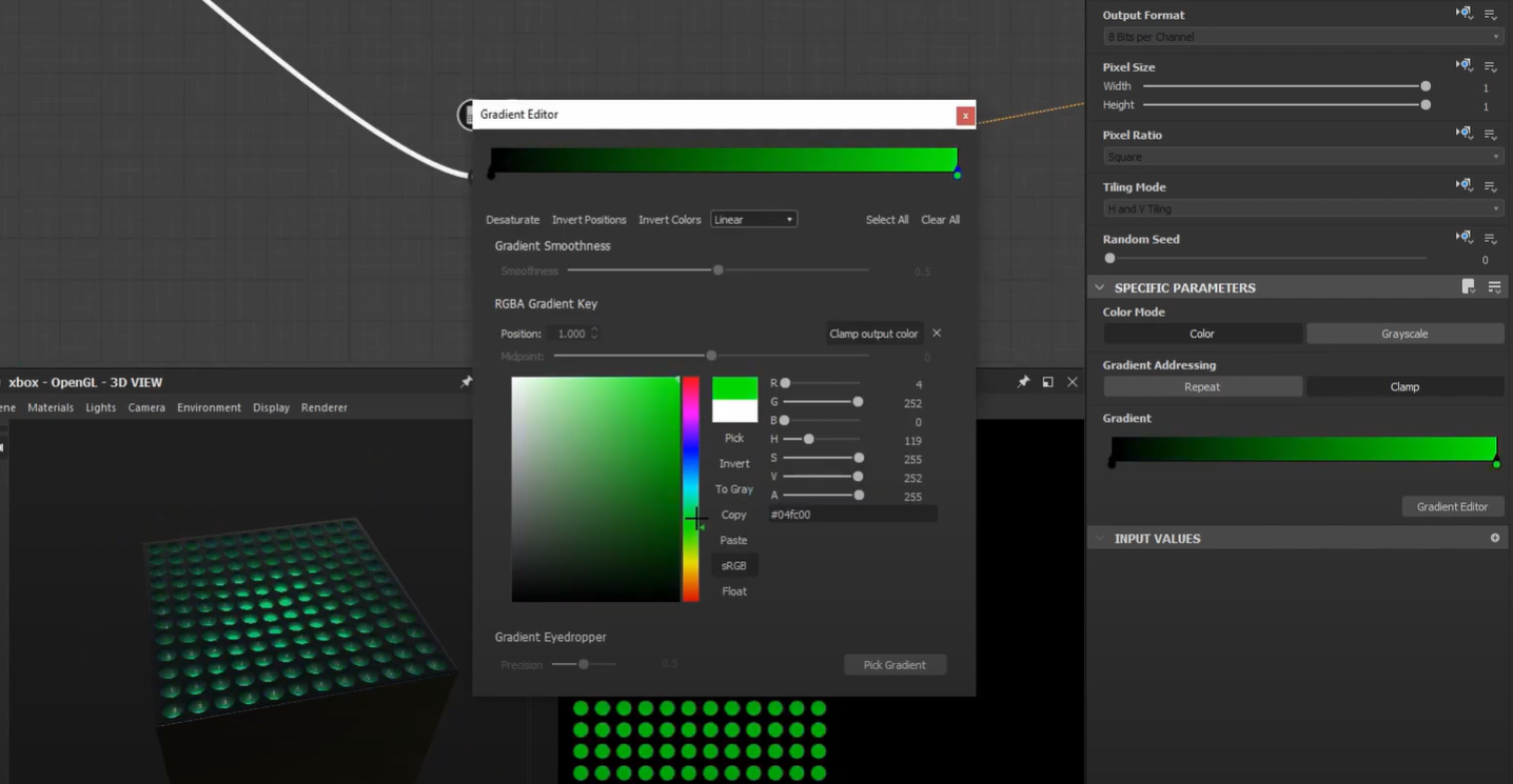
Connect our holes into a gradient map in order to set the color. You can set it to whatever color you want but in this case, I’ll stick to green. This will be the controller for the light inside the Xbox Series X.
Creating an Xbox Series X with Substance Designer | Part 2
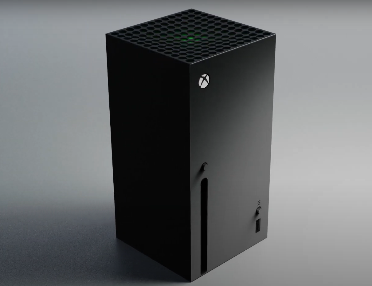
In this procedural modeling guide, we’ll pick up where we left off previously, and work on the decals and finer elements to our Xbox Series X inside of Substance Designer. We’ll then bring everything over to Blender and go over how to set up the textures and make use of displacement, to finally send it off to render at GarageFarm.NET.
Adding the logos and the disc drive
Add in a shape node, set the shape type to disc, connect that to a transform 2d node, then connect that to another transform 2d node, scale it down a bit, and set to no tiling, blend, and set to subtract. I accidentally switched the inputs here, you can select these connections and press X to invert them. This gives us control over the thickness of the shape.


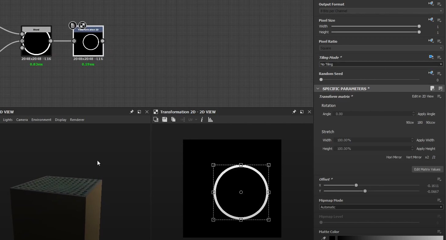
Connect the blend node to a transform 2D, turn off tiling, and now we can position it to wherever we want. Again, we can use a blend node to help us visualize where we want to position the logo.
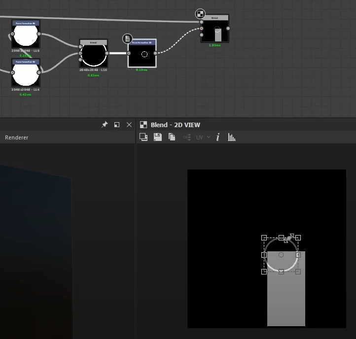
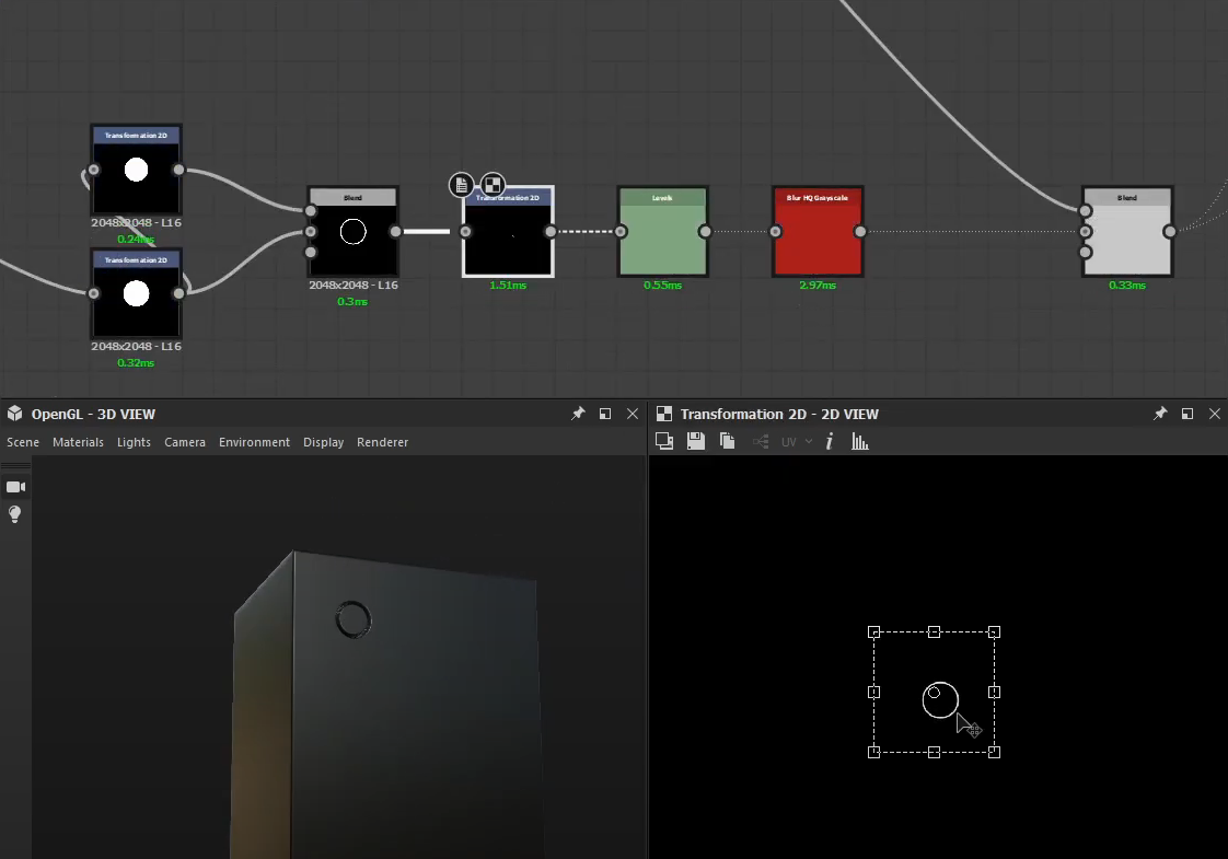
Run it through levels, invert, then blur it a bit to soften the edges before blending it in with our heightmap. After that, scale and place it wherever you want.
Import the Xbox logo, copy the transform 2d node that we used earlier, and set the blending type to add (linear dodge) to blend that with our emissive map. Soften the edges a bit using a blur color node. Plug that into our emissive output and then scale it down until it fits inside.
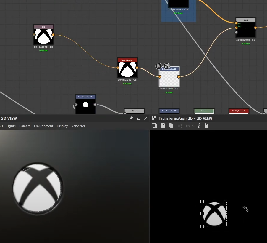
To make the logo pop a bit more, convert it to grayscale using a grayscale conversion node and then plug that into a normal node and combine it with our normal map. Inverted it using levels to make the logo extrude inward and play around with the normal intensity until it looks right.

Now import the Xbox text. Duplicate our transform node for the logo and plug the text into that and rotate it to 90 degrees. Set the color mode for the text to grayscale. Plug the logo into a transform 2d node and convert to grayscale then set the blending mode to add linear dodge. Position and scale down the logo until it looks right.
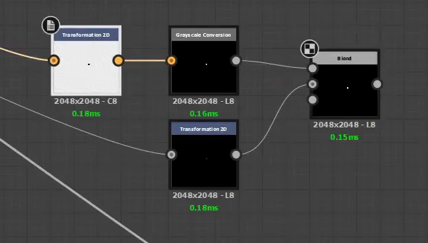
Blend that with our logo and use a transform 2d node to position it to the left side panel.
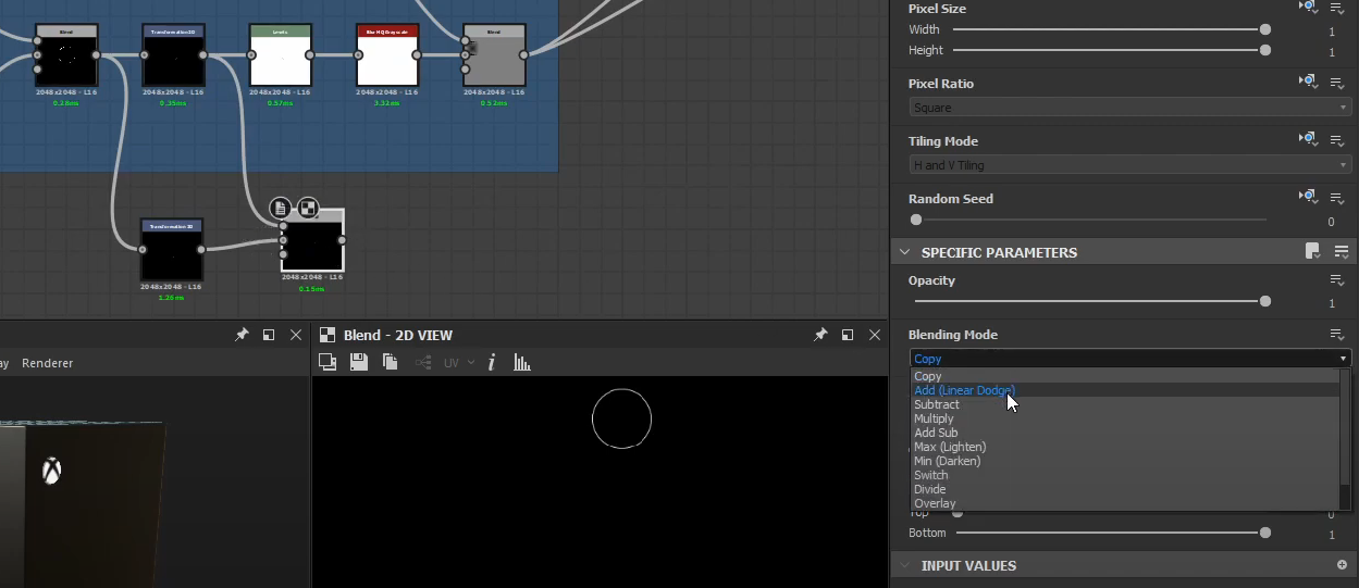
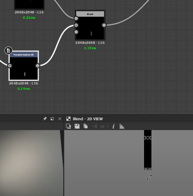
For the button of the Xbox, Duplicate the transform 2d node for the button and blend that with the original connection so we can visualize it better. Scale it down according to the reference picture. Plugin the inner part of the button into a transform 2d node, blend that in with our shape, and set the blending mode to max lighten to control how much the button extrudes. Add in a Levels node to act as our controller. Update our output nodes with our new height map and now we can see the button popping out. Add in a blur grayscale node to bevel the edge a bit. Play around with the slider in the levels node until it looks right.

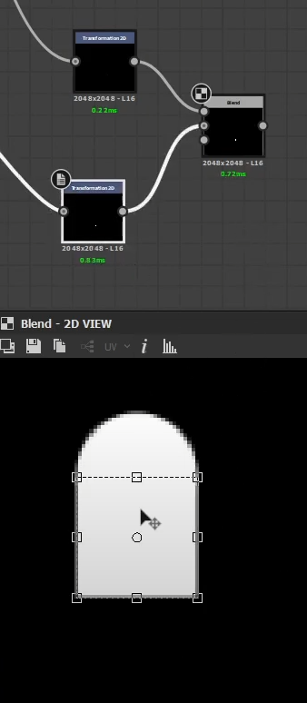
For the disc drive, duplicate the transform 2d for the disc shape and duplicate it again so we can plug in a square shape node. Blend them both together and scale the square until it fits right inside the circle. Invert it using levels and then blend that with our height map and set it to multiply. Stretch out the shape. Soften the edges a bit using a blur grayscale node. Use a histogram scan to tighten it up a bit, and then plug that through a bevel node.
Finishing the Details
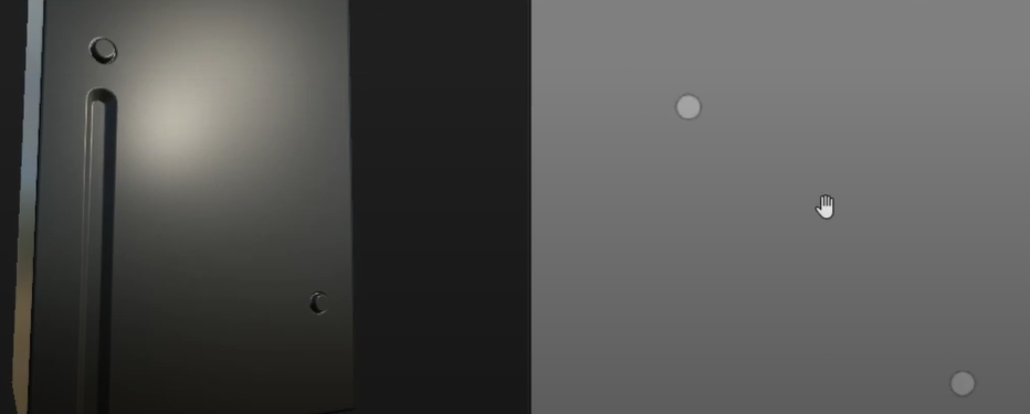
I added another button over here at the bottom right, adding it was just like how we did the first button. At this point, we’ve already covered the basic techniques to finish the Xbox, so we’ll go over the steps a bit faster.
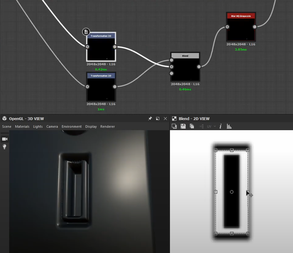
To make the USB port, connect the square shape node to a transform 2d, shape it into the size of a USB port, invert using levels, then blur to soften the edges. Blend that with our height map and set it to multiply to make a hole. Copy the hole shape and make it smaller, then do it again and make it even smaller so we can blend them both and subtract to make a hole. Duplicate another transform 2d, then blur and blend with add linear dodge. Duplicate the transform 2d nodes again, scale it down a bit, but this time rotate the second one by 90 degrees so we can blend and subtract to create this shape. Blur and run it through levels so we can control its height and then blend. Run the shape through levels and then blend with our hole so we can finish the USB port.
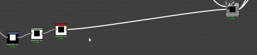

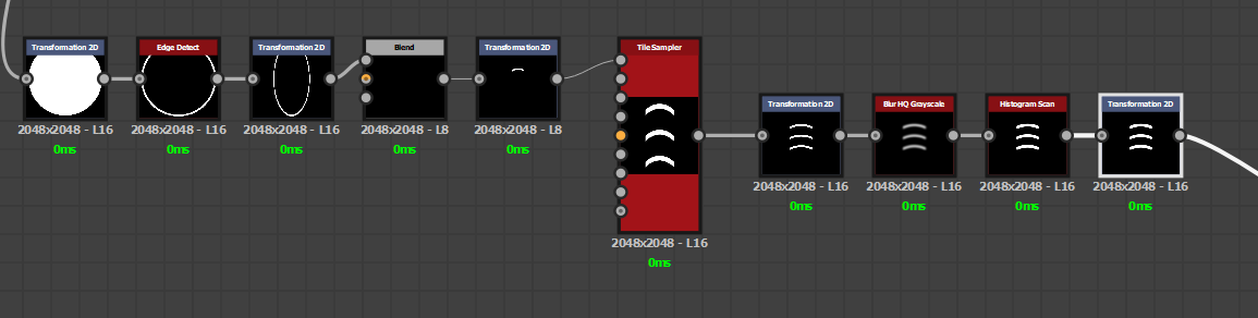
For the waves icon, add a transform 2d from our circle shape, run it through an edge detect node, scale down the shape a bit, use a blend node so we can crop out the top part, position it lower using a transform 2d, run it through a tile sampler so we can lay it out like this, stretch it down using a transform 2d, blur then run it through a histogram scan so it rounds out the edges, then use a transform 2d node again to scale and position it to where we want, invert using levels, and then blend using multiply to add it to our heightmap.
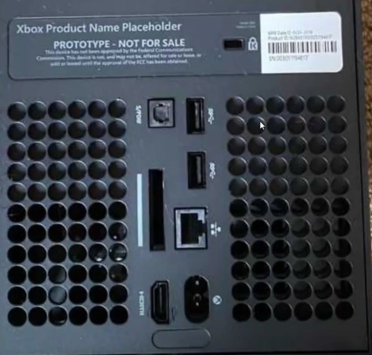
Feel free to use the techniques you’ve learned to do the ports at the back For the inner part of the USB port, duplicate the transform 2d node again and just scale the shape until it looks right.
Setting it up in Blender
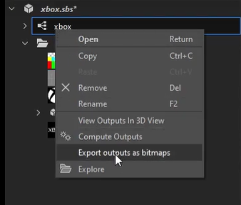
Export the textures by right-clicking on our package and export outputs as bitmaps. For rendering inside Blender, export the emissive, normal, and height maps.

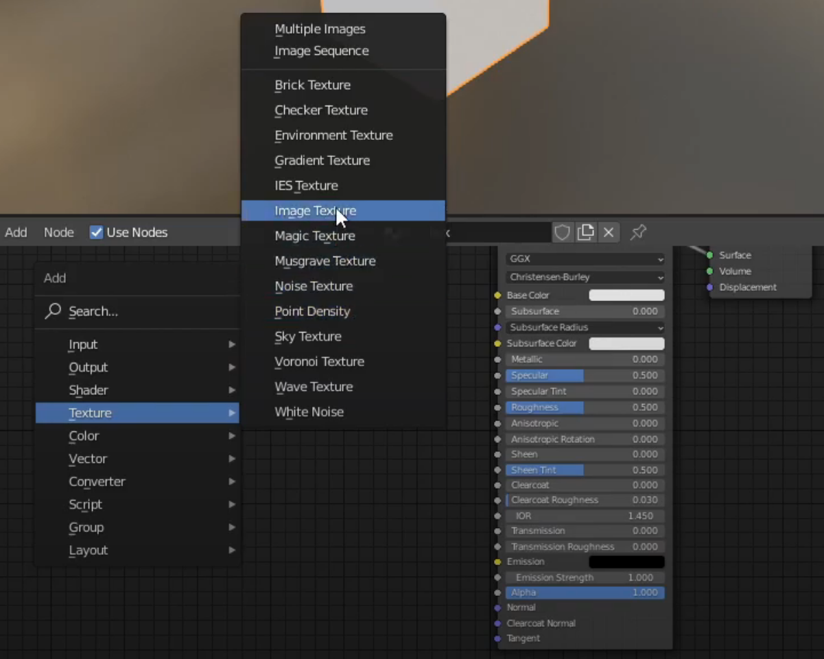
Back inside Blender’s node editor, add an image texture, select our normal map, set the color space to non-color, connect that into a normal map node, and then plug that into our normal input.
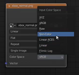
Set the base color to a really dark gray, set the metallic value to 1, and play around with the roughness value.

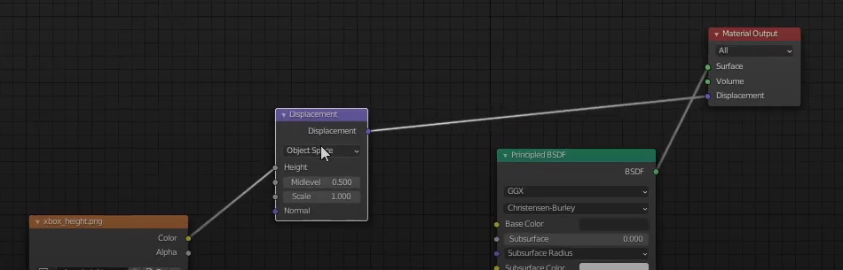
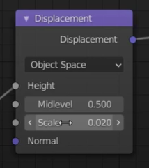
Import our emissive map and plug that into the emission input. Finally, import our height map, connect that to the height input of the displacement node, and then connect that to the displacement input of the material output.
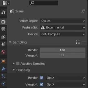
Set the render engine to Cycles, switch to the experimental feature set, and because I have an Nvidia RTX GPU, I’ll turn on Optix denoising. Add in a subsurf modifier, set it to simple, and click on the adaptive subdivision.
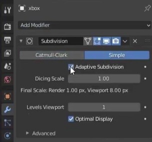
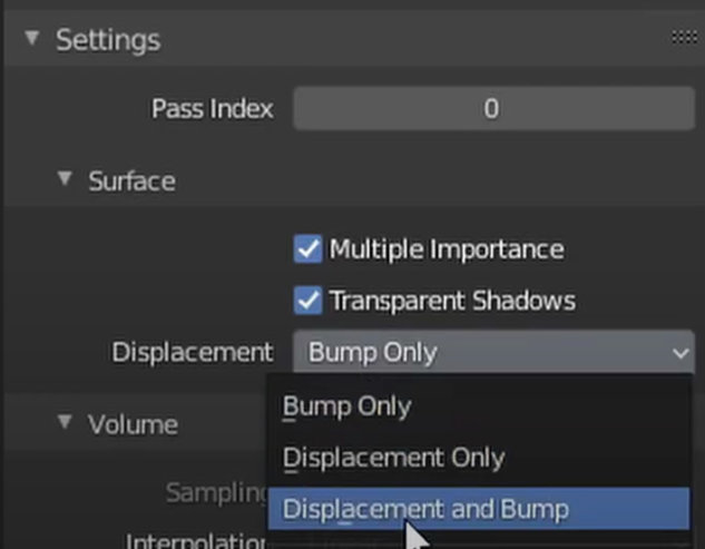
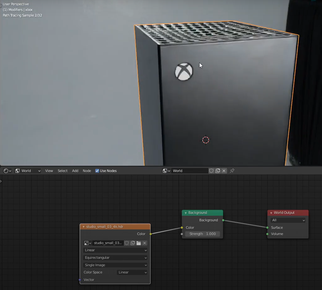
Tessellate our mesh by increasing the subdivision levels. In order to see the displacement, we have to switch to Rendered View. Then switch from Bump Only to Displacement and Bump. Lower down the scale in the displacement node. To see this better, we can import an HDR into our scene and there we go.

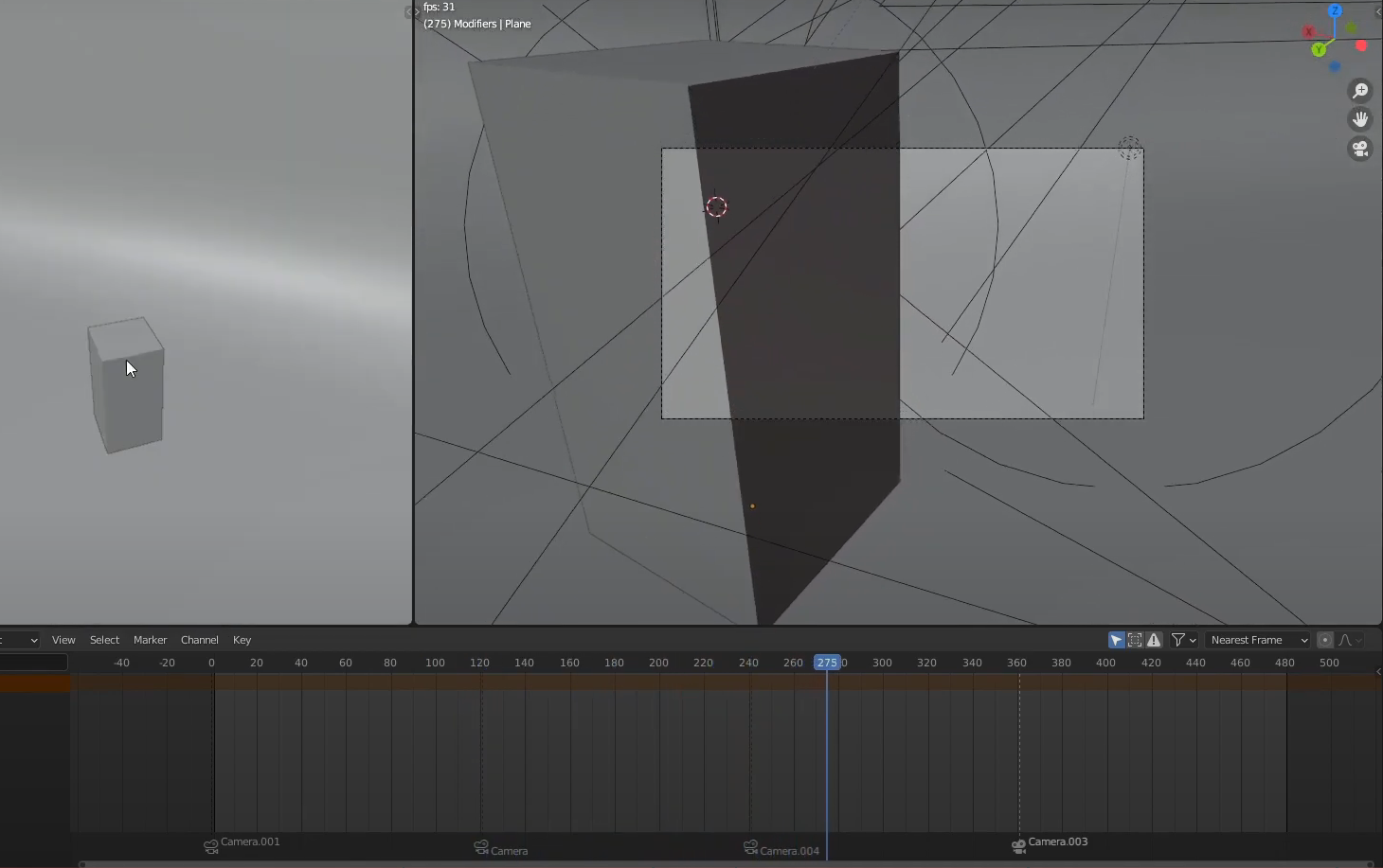
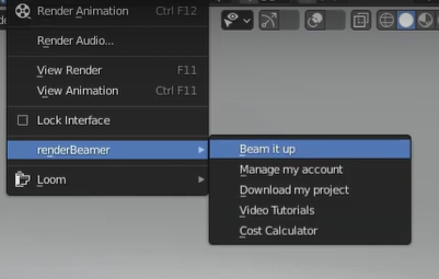
What I did here was set up some lights, cameras, and a quick little animation. As you can probably imagine, rendering a heavily tessellated mesh in animation can take a while so I’ll be rendering this on a render farm. Just gonna beam it up, render my animation, and just like that, we have our rendered frames.

If you’re interested in checking it out, head on over to our render farm. It’s super easy to use and can save you a lot of time. Anyway, I hope you learned a lot from this procedural modeling guide and the video series, and that you can apply these techniques inside Substance Designer into your own projects. Until next time, see you around.
Register Now and Get $50 FREE Credits!